The Challenge of Fine Line Screen Printing for Printable Electronics
Hiroki Sano of the NBC Meshtec Inc. R&D department discusses why the proper wire mesh must be selected for each printing project.
Screen-printing remains the most cost effective method for producing a wide variety of electronic components. Modern electronic components often require conductive line width as fine as 50µm or even narrower. To screen print such a fine conductive line, printers are required to utilize a mesh with the thinnest possible wire diameter, as this helps to minimize printing interference and to control paste deposit.
However, as a wire diameter gets thinner, its strength diminishes and the weaving process becomes challenging. Leading wire mesh manufacturers working to develop wire meshes designed for fine line printing must use higher strength materials. Moreover, in applications such as LTCC, capacitors, and inductors which require dimensional accuracy and stability, a high Young’s modulus wire is vital. Table A shows specific wire meshes designed for fine line printing applications introduced by NBC Meshtec Inc, Japan. The strength and Young’s modulus of the wire increases as you move down Table A (below). Fig. A shows a comparison of physical property between three different wire meshes for reference.
| Type | Material | Strength (N/mm²) | Mesh Count per Inch | Wire Diameter (µm) |
|---|---|---|---|---|
| M12/M13 | High Strength Stainless Steel | 1200 - 1300 | 730 | 13 |
| M12/M13 | High Strength Stainless Steel | 1200 - 1300 | 640 | 15 |
| M12/M13 | High Strength Stainless Steel | 1200 - 1300 | 500 | 16 |
| M30 | Super Strength Stainless Steel | 3000 - 3200 | 290 | 20 |
| M30 | Super Strength Stainless Steel | 3000 - 3200 | 325 | 16 |
| M30 | Super Strength Stainless Steel | 3000 - 3200 | 360 | 16 |
| W40 | Tungsten | 4000 | 290 | 20 |
| W40 | Tungsten | 4000 | 325 | 16 |
| W40 | Tungsten | 4000 | 430 | 13 |
Table A: NBC Meshtec Metal Series
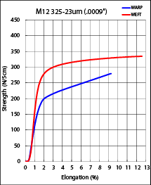
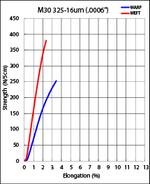
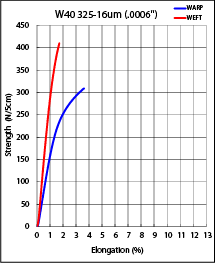 FIG. A: Comparison of three different wire meshes
It is important that the proper wire mesh specifications be selected for each individual printing project. Careful consideration should be given to the technical requirements of the print itself, as the print is greatly influenced by the specified mesh’s mesh count, thickness, percentage of open area, strength, dimensional accuracy and so on.
Calendered wire mesh (a process where the mesh is flattened by passing between rollers under high pressure) is a typical option designed to improve the mesh performance in several ways:
- The knuckles of the warp and weft wires are fastened tight and the mesh structure is stabilized to improve dimensional accuracy.
- The thinner the mesh, the lower the screen thickness, leading to a thinner paste deposit.
- The flattened knuckles of warp and weft wires improve the surface smoothness of the mesh, helping to improve screen Rz value and ultimately leading to better print resolution.
- Mesh thickness consistency is improved to ±1µm (vs. ±2µm with non-calendered mesh), resulting in a more even stencil and print.
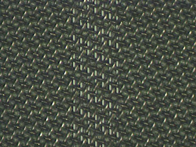
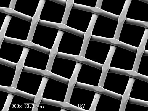 PHOTO A: M30 360-16µm calendered mesh
This precision process can be applied to all wire meshes discussed above. For instance, it is possible to calender the total thickness of a wire mesh down to the thickness of the individual wire diameter + 2µm. So for instance, the M30 360-16µm mesh shown in Photo A can be calendered down to a total mesh thickness of 18µm.
1. Solar cells (electrodes)
One well-known printable electronics application is photovoltaic or solar cells. Line straightness and uniform paste deposit are essential for printing solar cell surface electrodes. In order to optimize the electrical performance of the solar cell, the light receiving area on the surface of the cell must be maximized while, at the same time, enough paste must be deposited for proper resistivity. As a result, the industry trend has been toward ever narrower and taller lines. To achieve these printed lines, some solar cell manufacturers employ a double-print process. This is a process where two screens are used in succession in a print-on-print technique in order to build up the height of the printed line while still keeping it narrow. Needless to say, this double-print process requires extreme dimensional accuracy and repeatability from both the screen and the printing machine.
Most pastes used for printing on solar cells have a relatively high viscosity. Furthermore, squeegee speeds for solar printing are typically running at a rate of about 200mm/second. Consequently, a screen mesh with a small wire diameter and high open area (40%+) is generally required. The ideal meshes for such applications are M30 290-20µm or M30 360-16µm. Photo B and C below feature a screen and printed line using M30 360-16µm mesh.
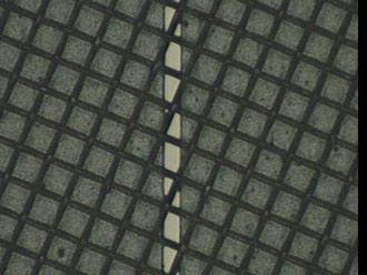 PHOTO B: Line width on screen 40µm
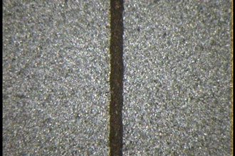 PHOTO C: Print output line width 44.6µm
The surface of the silicon wafer pictured in Photo D and E displays an irregularity referred to as ‘texture’. Printing on such a surface with variations of up to 15µm is considerably more difficult than printing on a smooth surface. Generally speaking, the rougher the texture, the greater the challenge.
For this type of printing, then, screens require a softer, high resolution emulsion with an increased thickness of about 15 to 20µm. This helps improve the gasket effect between the screen and the solar cell substrate.
Where finer lines are required, a screen mesh with even finer wire and a substrate with a smoother ‘texture’ are needed.
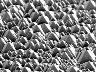 PHOTO D: Solar cell substrate surface – x2000 40 degree angle
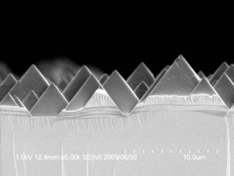 PHOTO E: Solar cell substrate cross-section – x5000 90 degree angle
2. Touch panel (frame extracting electrodes)
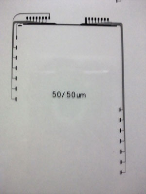
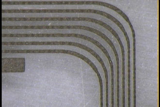
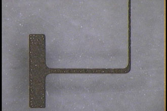
Oftentimes, untreated PET films, glasses or ITO films are used as printing substrates. With these types of hydrophilic materials, paste spreading can easily occur during printing. For this reason, the paste needs to be extremely high in both viscosity and thixotrophy. Typical printed line widths today are 70µm or narrower. Consequently, a wire mesh with a mesh count of 400 tpi (threads per inch) or higher, and a wire diameter 20µm or thinner, is highly recommended in order to optimize the paste deposit. Photo F features enlarged images of 50µm lines printed on untreated PET film using M12 500-19µm mesh. The most critical spots to print are the curved lines shown in Photo G and the single fine line shown in Photo H, as curved lines are prone to smearing and single lines tend to break or disconnect. Additionally, in a mass production setting, screen clogging is an issue with high viscosity paste.
3. LTCC electrode printing
Photo I shows 15µm line and 30µm space printing for an LTCC application. The substrate is a type of ceramic material referred to as ‘green sheet’. This porous material absorbs the paste solvent at the time of printing, minimizing spreading and making it possible to print extremely fine lines.
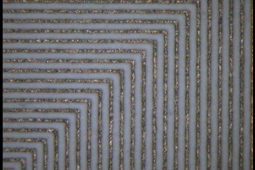 PHOTO I: 15µm line & 30µm space
4. Screen printing finer lines
When screen printing 30µm or finer lines, consider the following important recommendations:
- Choose a mesh count of 500 tpi or higher with a wire diameter 20µm or thinner.
- Select a high resolution emulsion with photopolymer size of less than 2 microns.
- Go with a glass mask (preferably chromium coated) for your artwork.
- Use a parallel light or Fresnel lens exposure unit for imaging.
- Opt for a precision printer with a suitable printing pressure that does not exert too much load (squeegee pressure) on the screen. A typical guideline for squeegee pressure is about 0.2 to 0.5 N/cm.
- Both screen making and printing should be done in a consistent (temperature and humidity controlled) environment.
- When possible, prepare/treat the surface of the substrate to minimize ink/paste spreading.
Photo J shows a screen with resolved 10µm lines and 20µm spaces using M12 730-13µm mesh and a 5µm EOM (Emulsion Over Mesh) thickness. While many companies are currently screen printing amazingly fine lines such as these with existing processes, research and development continues with the goal of pushing the limits of screen printing.
For assistance in meeting the challenges of fine line screen printing, please contact NBC Meshtec Americas at (800) 235-5056, or visit our team page to find the Technical Sales Representative for your area.


